- 您现在的位置:买卖IC网 > Sheet目录3872 > PIC16F627-04/SO (Microchip Technology)IC MCU FLASH 1KX14 COMP 18SOIC
PIC16F62X
DS40300C-page 138
Preliminary
2003 Microchip Technology Inc.
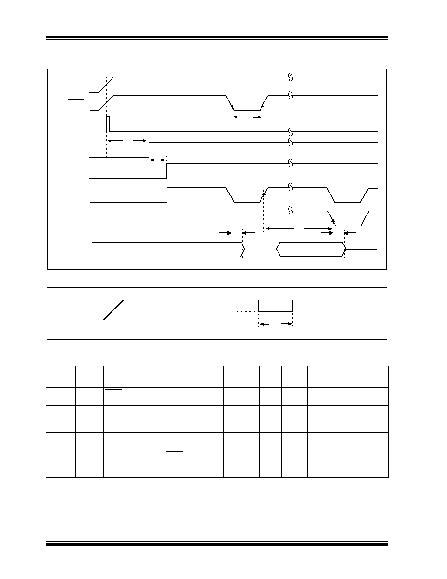
FIGURE 17-8:
RESET, WATCHDOG TIMER, OSCILLATOR START-UP TIMER AND POWER-UP
TIMER TIMING
FIGURE 17-9:
BROWN-OUT DETECT TIMING
TABLE 17-6:
RESET, WATCHDOG TIMER, OSCILLATOR START-UP TIMER AND POWER-UP
TIMER REQUIREMENTS
Param
No.
Sym
Characteristic
Min
Typ
Max
Units
Conditions
30
TmcL
MCLR Pulse Width (low)
2000
TBD
—
TBD
—
TBD
ns
ms
V
DD = 5V, -40°C to +85°C
Extended temperature
31
Twdt
Watchdog Timer Timeout Period
(No Prescaler)
7
TBD
18
TBD
33
TBD
ms
V
DD = 5V, -40°C to +85°C
Extended temperature
32
Tost
Oscillation Start-up Timer Period
—
1024T
OSC
——
T
OSC = OSC1 period
33*
Tpwrt
Power-up Timer Period
28
TBD
72
TBD
132
TBD
ms
V
DD = 5V, -40°C to +85°C
Extended temperature
34
TIOZ
I/O Hi-impedance from MCLR Low
or Watchdog Timer Reset
——
2.0
s
35
T
BOD
Brown-out Detect pulse width
100
—
sVDD ≤ VBOD (D005)
*
These parameters are characterized but not tested.
Data in “Typ” column is at 5.0V, 25
°C unless otherwise stated. These parameters are for design guidance only and are not
tested.
V
DD
MCLR
Internal
POR
PWRT
Timeout
OSC
Timeout
Internal
RESET
Watchdog
Timer
RESET
33
32
30
31
34
I/O Pins
34
V
DD
V
BOD
35
发布紧急采购,3分钟左右您将得到回复。
相关PDF资料
PIC16C58B-20I/P
IC MCU OTP 2KX12 18DIP
PIC24FJ16GA002-I/SS
IC PIC MCU FLASH 16K 28-SSOP
PIC16C55A-04I/SO
IC MCU OTP 512X12 28SOIC
PIC16CR77-I/ML
IC PIC MCU 8KX14 44QFN
PIC16CR74T-I/PT
IC PIC MCU 4KX14 44TQFP
PIC16F627A-I/ML
IC MCU FLASH 1KX14 EEPROM 28QFN
PIC24F08KL401-I/P
IC MCU 16BIT 8KB FLASH 20-PDIP
PIC16LF727-I/P
IC PIC MCU FLASH 8K 1.8V 40-DIP
相关代理商/技术参数
PIC16F627-04/SO
制造商:Microchip Technology Inc 功能描述:8BIT FLASH MCU SMD 16F627 SOIC18
PIC16F627-04/SO
制造商:Microchip Technology Inc 功能描述:Microcontroller IC Number of I/Os:16
PIC16F627-04/SS
功能描述:8位微控制器 -MCU 1.75KB 224 RAM 16I/O 4MHz SSOP20 RoHS:否 制造商:Silicon Labs 核心:8051 处理器系列:C8051F39x 数据总线宽度:8 bit 最大时钟频率:50 MHz 程序存储器大小:16 KB 数据 RAM 大小:1 KB 片上 ADC:Yes 工作电源电压:1.8 V to 3.6 V 工作温度范围:- 40 C to + 105 C 封装 / 箱体:QFN-20 安装风格:SMD/SMT
PIC16F627-04E/P
功能描述:8位微控制器 -MCU 1.75KB 224 RAM 16I/O RoHS:否 制造商:Silicon Labs 核心:8051 处理器系列:C8051F39x 数据总线宽度:8 bit 最大时钟频率:50 MHz 程序存储器大小:16 KB 数据 RAM 大小:1 KB 片上 ADC:Yes 工作电源电压:1.8 V to 3.6 V 工作温度范围:- 40 C to + 105 C 封装 / 箱体:QFN-20 安装风格:SMD/SMT
PIC16F627-04E/SO
功能描述:8位微控制器 -MCU 1.75KB 224 RAM 16I/O 4MHz Ext Temp SOIC18 RoHS:否 制造商:Silicon Labs 核心:8051 处理器系列:C8051F39x 数据总线宽度:8 bit 最大时钟频率:50 MHz 程序存储器大小:16 KB 数据 RAM 大小:1 KB 片上 ADC:Yes 工作电源电压:1.8 V to 3.6 V 工作温度范围:- 40 C to + 105 C 封装 / 箱体:QFN-20 安装风格:SMD/SMT
PIC16F627-04E/SS
功能描述:8位微控制器 -MCU 1.75KB 224 RAM 16I/O 4MHz Ext Temp SSOP20 RoHS:否 制造商:Silicon Labs 核心:8051 处理器系列:C8051F39x 数据总线宽度:8 bit 最大时钟频率:50 MHz 程序存储器大小:16 KB 数据 RAM 大小:1 KB 片上 ADC:Yes 工作电源电压:1.8 V to 3.6 V 工作温度范围:- 40 C to + 105 C 封装 / 箱体:QFN-20 安装风格:SMD/SMT
PIC16F627-04I/P
功能描述:8位微控制器 -MCU 1.75KB 224 RAM 16I/O 4MHz IndTemp PDIP18 RoHS:否 制造商:Silicon Labs 核心:8051 处理器系列:C8051F39x 数据总线宽度:8 bit 最大时钟频率:50 MHz 程序存储器大小:16 KB 数据 RAM 大小:1 KB 片上 ADC:Yes 工作电源电压:1.8 V to 3.6 V 工作温度范围:- 40 C to + 105 C 封装 / 箱体:QFN-20 安装风格:SMD/SMT
PIC16F627-04I/P
制造商:Microchip Technology Inc 功能描述:IC 8BIT FLASH MCU 16F627 DIP18